

I will first start off by saying that this was a mode I had been contemplating for a while. I read in previous post that it could be done but wasn't really sure if it was true or not. I noticed that I was doing the same thing as a lot of people would do, get all of the parts (thanks L3GDKANG) but never install them. After holding on the parts for about 10 months, I decided I would finally get started. Parts that will be needed are:
LS digital climate control and LS harness plug that goes in back of climate control
Ambient temp sensor & screw for bracket (fr of radiator)
Heater core sensor & metal clip (under heater core)
Photo-sensor (top of dash)
Mode control motor (under steering wheel panel on right side)
Soldering gun
Shrink-wrap
Small butane torch or I just used .99 cents lighter
18 gauge wire (as many diff colors as possible will help, i just used red/black)
Wire ties
Flex Loom
Electrical Tape
Continuity tester (if you dont follow directions, there are some wires which are same color and you will have to figure out which wires are used/not used)
When you purchase these parts or pull them, make sure you get the wiring harnesses that plug into them as well. Let me start off by given credit to previous forum members who had done this mode and here some past post that you can reference.
http://www.acura-legend.com/forums/showthread.php?t=47596&highlight=climate+control+conversion
http://www.acura-legend.com/forums/showthread.php?t=48704&highlight=climate+control+conversion
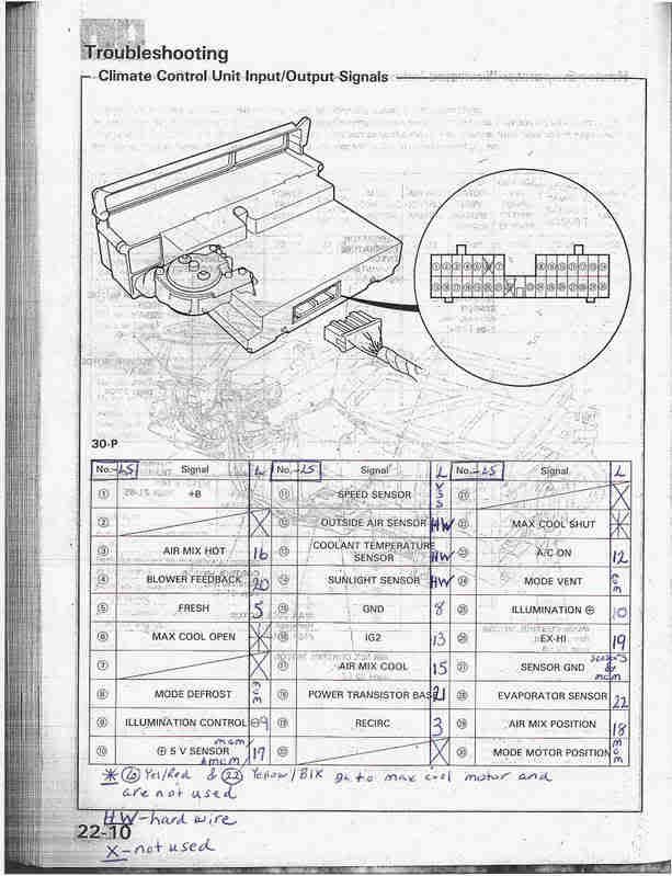
I will sum all of the previous post up here plus discuss some issues that I encountered. I will also post pictures (some aren't as clear as i hoped) and clear up some issues that gave me a few problems into one DIY post. Before you start installing any parts I would first print off all the material below. You will need to familiarize yourself with the climate control (manual and digital) and how they actually work. It will make it much easier in the long run when you start cross-referencing wires and if you need to troubleshoot later on as well. I have provided the wiring diagrams indicating which wires go from the L harness to the LS harness. I will say its not that hard to do, but I did find some errors in the Legend manual which did leave me some what confused at times which lets you know I spent way to much time on these diagrams. You will need both manuals in order to complete the wiring as neither manual gives all of the information I needed. The Legend manual diagrams were useful to determine what colors the wires are and the Helms manual diagrams were useful to determine where the wires go. Below are wiring harness diagrams for L and LS.
![Image]()
In this link you will find wiring circuit diagrams for L and LS which will show the colors of wires, explanation of sensors and motors and how each system works and also diagrams where each part is located as well.
http://home.mchsi.com/~legendcoupe/
Disclaimer
I'm sorry to say that I must include the following disclaimer. You accept full responsibility for performing this mod on your car. While these instructions are accurate to the best of my knowledge, I cannot be held responsible for any errors that they may contain. I also cannot be held responsible for any ill effects due causes including, but not limited to the following:
· Improper following of instructions
· Errors in the instructions
· Differences in your vehicle from mine
· Any other cause
That's it and we are done with that, let's begin.
***Disconnect battery before starting any electrical work***
![Image]()
All panels under the steering wheel and glove box should be removed before starting this mode. It will allow you access to all areas needed. This was easy for me as all of my panels were already removed because I'm changing from Type F to all black interior. The old manual climate control and vents will need to be removed as well to give you access to wiring.
Installing Motors & Sensors
The first thing I would suggest is installing the mode control motor. For some that are wondering if you can just rewire the current mode control motor on the L model, the answer is no because it will not work. This is the hardest thing to do, as you will be on your back in awkward positions so I would get this out of the way first. It is very hard to get to so I removed the brown box (power lock) next to it by removing the two gold screws. You will need a ratchet set with an extender. Once the brown box is removed, it will give you a little more room to get to the old mode control motor but not much. You will need a small screwdriver to remove four small screws on the outer edge of the mode control motor. If you look at the new mode control motor you have, it will give you an idea of where the screws are. Installation is the reverse of removing.
![Image]()
![Image]()
![Image]()
Next, install the heater core sensor. It should be rectangular and have two orange wires coming out it. Under the glove box to the left you will see the heater core. If you look at the underside of the heater you will see a notch where the heater core sensor is normally installed on LS models. Some people in the past have just super glued or taped the sensor to the underside of the heater core. Since I was all in at this point I figured I would do thing correctly, even if it took a little more time, to ensure everything worked correctly. You can take the soldering iron and start to make a small hole in the bottom of the heater core by melting the plastic. Take your time making the hole for the heater core sensor so that the hold would be correct size. You want to make sure you don't damage the heater core so be patient. Melt the plastic a little at a time and then try to fit the heater core sensor in place. Do this little by little until you get the hole the perfect size for the heater core sensor to fit. After the hole was just the right side, I installed the metal clip and the heater core temp sensor. The metal clip pushes the sensor snugly against the heater core. Push the metal clip in until it snaps into place and then you are done.
![Image]()
![Image]()
![Image]()
![Image]()
Ok, you are halfway there installing motors and sensors and only have two more to go. The photo sensor is installed on the top of the dash. To get the blank piece out, use a cloth so the dash wouldn't be damaged and a small flat head screwdriver. You can basically just pry it out. To install the photo sensor, you will need a screwdriver and a coat hanger and tape the two together. If you reach your hand over the vent in the dash and put your finger in the opening for the photo sensor on the top of the dash, there will be a small crease that you can fish the wire thru. It takes a little time to get the wire through but trust me save a lot of time in not having to remove the dashboard.
![Image]()
![Image]()
![Image]()
![Image]()
The last sensor to install is in front of the radiator. The L models already come pre-wired for ambient temperature sensor. The connector will be taped down with black tape. All you have to do is the remove the tape for the harness. When you pulled the ambient temp sensor, it should be attached to a bracket and hopefully you kept the screw as well. You will just need to screw the ambient temperature bracket on the bracket in front of the radiator and then hook up the connectors. Now you are finally done installing the motors and sensors needed.
![Image]()
![Image]()
![Image]()
![Image]()
Wiring
Next will come the tedious part of wiring. It's not hard at all but does take time if you do it correctly. I wouldn't use t-taps because they may come loose and electrical tape is out of the questions. For the time spent on the mod and for the security of not having to go back in because wires have come loose, I would highly suggest soldering and shrink wrapping every wire possible. It will take a little more time but will be well worth it in the end. I first stripped all of the wires on the LS harness that will be used. Wire #6 (yellow/black) and Wire #22 (yellow/red) will not be used.
![Image]()
***Doing the wiring took me two days to complete all of the soldering. Once I was done on day 1, I taped all of the loose wires so none of the wires would touch to preventing anything from shorting out***
****DO NOT CUT THE L HARNESS OFF YET***
Hope you didn't do this already but if you did cut the wire its not life or death but it will take you a little longer because there are wires with duplicate colors and you will have to figure out which ones you use and which ones will not be used. You will now need the continuity tester in the parts list to seperate the duplicaet wires. Personally while connecting the wires of the different motors and sensors (mode control, air mix, etc. I tape and grouped my wires off and labeled them so it would be easier to determine which wire went to what in case any troubleshooting was needed.
![Image]()
I would start off by cutting the wires that will not be used and tie them off so they are not in your way and not connected by mistake. Wires not used:
1 - Yellow/Green
2 - Brown
5 - Blue/Red
6 - Blue
7 - Yellow
11 - Green
Once these wires are out of the way you can start connecting the other wires. Instead of cutting the harness and all of the wires at once, it will be easier if you cut one wire at a time. This way you can match up the corresponding wires to the LS harness easily. These wires should basically be the same colors and if you have familiarized yourself with the wiring diagrams, this should be pretty straightforward.
L Harness Wire # Color LS Harness Wire # Color
Rec 3 Blue/Orange 19 Blue/Orange
***Legend Manual error. It shows wires 22-8 two times. One of the 22-8 wires is actually 22-3, which comes from the recirculation control motor***
Fresh 4 Blue/Green 5 Blue/Green
GRD 8 Black 15 Black
Ill Cont + 9 Red 9 Black
Ill Cont - 10 Red/Black 25 Red/Black
***This was confusing because the wire colors are different from wiring diagram in Legend manual. L harness wire 9 is red but there is no red wire to connect on LS harness wire 9. It is black instead of red***
AC on 12 Blue/Red 23 Blue/Red
IG2 13 Black/Yellow 16 Black/Yellow
Sensor Grd 14 Black 27 Black
Air Mix Cool 15 Red/White 17 Red/White
***Legend Manual Error. This wire on LS wiring diagram is marked as 30-1 but should be 30-17, which come from air mix control motor***
Air Mix Hot 16 Red/Yellow 3 Red/Yellow
+5 17 Green/Red 10 Green/Red
Air Mix Post 18 Green/White 29 Green/White
Blower High 19 Orange/White 26 Orange/White
Pwr Trans In 20 Blue/Black 4 Blue/Black
Pwr Trans Out 21 Light GR/Black 18 Light GR/Black
Evap Sensor 22 Brown 28 Brown
At this point all 22 wires from the L plug harness should be used (16 wires connected and 6 wires not used)
Next will be hardwiring of mode control motor and sensors directly to the LS harness. You will need to add wire to extend wires from sensor to plug into wiring harness.
![Image]()
![Image]()
Mode Control Motor
From MCM Plug LS Harness & #
Red/Green Red/Green 24
Blue/White Blue/White 8
Green/Yellow Green/Yellow 30
Black Black 27
((VSS & Outside Ambient Temperature Sensor - ECU & Right Kick Panel))
from VSS LS Harness & #
Yellow/Red Yellow/Red 11
I taped into the VSS wire and did not cut it. To get to the VSS you will need to open the ECU. There are four nuts that needs to be removed and then you can lift the cover to access the wires. I did this by taking a sharp razor blade and gently removing the plastic from the wire until the wire was exposed. I exposed about one inch of wire with cutting it. I was able to solder the connection for a good connect but wasn't able to shrink-wrap so I just used electrical tape.
![Image]()
![Image]()
Outside Ambient Temp Sensor
Also in the right hand side of the kick, the wire for the ambient temperature sensor comes from the front of the radiator. There will be a pink wire and a black wire that go into a blue plug. I did the same as I did for the VSS wire and exposed the wires where I could solder them and then wrapped with electrical tape. I didn't cut either of these wires so therefore I couldn't shrink-wrap the wires.
From Ambient Temp Sensor LS Harness & #
Pink Pink 12
Black Black 27
![Image]()
Sunlight Sensor
You should have run wires for this sensor thru the opening above the vents from the dash.
From Sunlight Sensor LS Harness & #
Orange Orange 14
Green/Red Green/Red 10 (this also connects to green red wire mcm/air mix control)
Heater Core Temp Sensor
You will see two orange wires coming from heater core temperature sensor, which you installed on the bottom of the heater core. After the connector one orange wire with go to light blue wire and the other orange will go to black wire.
From Heater Core Sensor LS Harness & #
Light blue Light Blue 13
Black Black 27
![Image]()
Evaporator Temperature Sensor
This sensor was pre-wired on the car. We connected it to the LS harness already (brown wire). This black wire leading from this sensor will needed to be connected so it is ground.
From Evap Temp Sensor LS Harness & #
Black Black 27
Brown 22 (L harness) Brown 28
![Image]()
Now all of the sensors and mode control motor is wired. All wires on the LS plug should be used except for #6 & #22. Hopefully all wires were soldered and shrink-wrapped. At this point I personally went back and rechecked my wiring three separate times in order to confirm all wires were connected correctly. After all of this time I wanted to make sure nothing was going to short or wires were going to fry. If you labeled, your wires as I suggested previously, going to back to recheck them should be fairly easy and straightforward. After you are 110% sure all wires are connected correctly, I hooked the battery back up and gave it power before putting all panels back to make sure everything was working correctly. If everything is hooked up correctly, your new LS digital climate control should be fully functional. You can put the digital climate control in self- diagnosis mode to ensure all sensors and mode control motor is wired correctly. You can test each functions separately making sure your defrost, vents (up and lower), air and heat work as well. If it is working properly, CONGRADULATIONS! You are one of the very few who had the patience and determination to complete the mod.
![Image]()
If not, then you will need to go back and check all of your connections to make sure all wires are connected to the correct wire and also that all of you wire connections are together (you did solder the wires and not use t-taps or electrical tape, right?). If so you can post your questions on forums to get help. Once everything is working properly, gather all of the wires together and tie them off.
![Image]()
Now you can reinstall everything that was taken apart and you are ready to enjoy your new digital climate control and you are one step closer to an LS model. Coming soon will be a DIY of JDM navigation console with fully functional upper and lower vents & I will post final pics of my jdm climate control mounted in the console.
LS digital climate control and LS harness plug that goes in back of climate control
Ambient temp sensor & screw for bracket (fr of radiator)
Heater core sensor & metal clip (under heater core)
Photo-sensor (top of dash)
Mode control motor (under steering wheel panel on right side)
Soldering gun
Shrink-wrap
Small butane torch or I just used .99 cents lighter
18 gauge wire (as many diff colors as possible will help, i just used red/black)
Wire ties
Flex Loom
Electrical Tape
Continuity tester (if you dont follow directions, there are some wires which are same color and you will have to figure out which wires are used/not used)
When you purchase these parts or pull them, make sure you get the wiring harnesses that plug into them as well. Let me start off by given credit to previous forum members who had done this mode and here some past post that you can reference.
http://www.acura-legend.com/forums/showthread.php?t=47596&highlight=climate+control+conversion
http://www.acura-legend.com/forums/showthread.php?t=48704&highlight=climate+control+conversion
I will sum all of the previous post up here plus discuss some issues that I encountered. I will also post pictures (some aren't as clear as i hoped) and clear up some issues that gave me a few problems into one DIY post. Before you start installing any parts I would first print off all the material below. You will need to familiarize yourself with the climate control (manual and digital) and how they actually work. It will make it much easier in the long run when you start cross-referencing wires and if you need to troubleshoot later on as well. I have provided the wiring diagrams indicating which wires go from the L harness to the LS harness. I will say its not that hard to do, but I did find some errors in the Legend manual which did leave me some what confused at times which lets you know I spent way to much time on these diagrams. You will need both manuals in order to complete the wiring as neither manual gives all of the information I needed. The Legend manual diagrams were useful to determine what colors the wires are and the Helms manual diagrams were useful to determine where the wires go. Below are wiring harness diagrams for L and LS.
In this link you will find wiring circuit diagrams for L and LS which will show the colors of wires, explanation of sensors and motors and how each system works and also diagrams where each part is located as well.
http://home.mchsi.com/~legendcoupe/
Disclaimer
I'm sorry to say that I must include the following disclaimer. You accept full responsibility for performing this mod on your car. While these instructions are accurate to the best of my knowledge, I cannot be held responsible for any errors that they may contain. I also cannot be held responsible for any ill effects due causes including, but not limited to the following:
· Improper following of instructions
· Errors in the instructions
· Differences in your vehicle from mine
· Any other cause
That's it and we are done with that, let's begin.
***Disconnect battery before starting any electrical work***

All panels under the steering wheel and glove box should be removed before starting this mode. It will allow you access to all areas needed. This was easy for me as all of my panels were already removed because I'm changing from Type F to all black interior. The old manual climate control and vents will need to be removed as well to give you access to wiring.
Installing Motors & Sensors
The first thing I would suggest is installing the mode control motor. For some that are wondering if you can just rewire the current mode control motor on the L model, the answer is no because it will not work. This is the hardest thing to do, as you will be on your back in awkward positions so I would get this out of the way first. It is very hard to get to so I removed the brown box (power lock) next to it by removing the two gold screws. You will need a ratchet set with an extender. Once the brown box is removed, it will give you a little more room to get to the old mode control motor but not much. You will need a small screwdriver to remove four small screws on the outer edge of the mode control motor. If you look at the new mode control motor you have, it will give you an idea of where the screws are. Installation is the reverse of removing.


Next, install the heater core sensor. It should be rectangular and have two orange wires coming out it. Under the glove box to the left you will see the heater core. If you look at the underside of the heater you will see a notch where the heater core sensor is normally installed on LS models. Some people in the past have just super glued or taped the sensor to the underside of the heater core. Since I was all in at this point I figured I would do thing correctly, even if it took a little more time, to ensure everything worked correctly. You can take the soldering iron and start to make a small hole in the bottom of the heater core by melting the plastic. Take your time making the hole for the heater core sensor so that the hold would be correct size. You want to make sure you don't damage the heater core so be patient. Melt the plastic a little at a time and then try to fit the heater core sensor in place. Do this little by little until you get the hole the perfect size for the heater core sensor to fit. After the hole was just the right side, I installed the metal clip and the heater core temp sensor. The metal clip pushes the sensor snugly against the heater core. Push the metal clip in until it snaps into place and then you are done.


Ok, you are halfway there installing motors and sensors and only have two more to go. The photo sensor is installed on the top of the dash. To get the blank piece out, use a cloth so the dash wouldn't be damaged and a small flat head screwdriver. You can basically just pry it out. To install the photo sensor, you will need a screwdriver and a coat hanger and tape the two together. If you reach your hand over the vent in the dash and put your finger in the opening for the photo sensor on the top of the dash, there will be a small crease that you can fish the wire thru. It takes a little time to get the wire through but trust me save a lot of time in not having to remove the dashboard.


The last sensor to install is in front of the radiator. The L models already come pre-wired for ambient temperature sensor. The connector will be taped down with black tape. All you have to do is the remove the tape for the harness. When you pulled the ambient temp sensor, it should be attached to a bracket and hopefully you kept the screw as well. You will just need to screw the ambient temperature bracket on the bracket in front of the radiator and then hook up the connectors. Now you are finally done installing the motors and sensors needed.


Wiring
Next will come the tedious part of wiring. It's not hard at all but does take time if you do it correctly. I wouldn't use t-taps because they may come loose and electrical tape is out of the questions. For the time spent on the mod and for the security of not having to go back in because wires have come loose, I would highly suggest soldering and shrink wrapping every wire possible. It will take a little more time but will be well worth it in the end. I first stripped all of the wires on the LS harness that will be used. Wire #6 (yellow/black) and Wire #22 (yellow/red) will not be used.

***Doing the wiring took me two days to complete all of the soldering. Once I was done on day 1, I taped all of the loose wires so none of the wires would touch to preventing anything from shorting out***
****DO NOT CUT THE L HARNESS OFF YET***
Hope you didn't do this already but if you did cut the wire its not life or death but it will take you a little longer because there are wires with duplicate colors and you will have to figure out which ones you use and which ones will not be used. You will now need the continuity tester in the parts list to seperate the duplicaet wires. Personally while connecting the wires of the different motors and sensors (mode control, air mix, etc. I tape and grouped my wires off and labeled them so it would be easier to determine which wire went to what in case any troubleshooting was needed.

I would start off by cutting the wires that will not be used and tie them off so they are not in your way and not connected by mistake. Wires not used:
1 - Yellow/Green
2 - Brown
5 - Blue/Red
6 - Blue
7 - Yellow
11 - Green
Once these wires are out of the way you can start connecting the other wires. Instead of cutting the harness and all of the wires at once, it will be easier if you cut one wire at a time. This way you can match up the corresponding wires to the LS harness easily. These wires should basically be the same colors and if you have familiarized yourself with the wiring diagrams, this should be pretty straightforward.
L Harness Wire # Color LS Harness Wire # Color
Rec 3 Blue/Orange 19 Blue/Orange
***Legend Manual error. It shows wires 22-8 two times. One of the 22-8 wires is actually 22-3, which comes from the recirculation control motor***
Fresh 4 Blue/Green 5 Blue/Green
GRD 8 Black 15 Black
Ill Cont + 9 Red 9 Black
Ill Cont - 10 Red/Black 25 Red/Black
***This was confusing because the wire colors are different from wiring diagram in Legend manual. L harness wire 9 is red but there is no red wire to connect on LS harness wire 9. It is black instead of red***
AC on 12 Blue/Red 23 Blue/Red
IG2 13 Black/Yellow 16 Black/Yellow
Sensor Grd 14 Black 27 Black
Air Mix Cool 15 Red/White 17 Red/White
***Legend Manual Error. This wire on LS wiring diagram is marked as 30-1 but should be 30-17, which come from air mix control motor***
Air Mix Hot 16 Red/Yellow 3 Red/Yellow
+5 17 Green/Red 10 Green/Red
Air Mix Post 18 Green/White 29 Green/White
Blower High 19 Orange/White 26 Orange/White
Pwr Trans In 20 Blue/Black 4 Blue/Black
Pwr Trans Out 21 Light GR/Black 18 Light GR/Black
Evap Sensor 22 Brown 28 Brown
At this point all 22 wires from the L plug harness should be used (16 wires connected and 6 wires not used)
Next will be hardwiring of mode control motor and sensors directly to the LS harness. You will need to add wire to extend wires from sensor to plug into wiring harness.


Mode Control Motor
From MCM Plug LS Harness & #
Red/Green Red/Green 24
Blue/White Blue/White 8
Green/Yellow Green/Yellow 30
Black Black 27
((VSS & Outside Ambient Temperature Sensor - ECU & Right Kick Panel))
from VSS LS Harness & #
Yellow/Red Yellow/Red 11
I taped into the VSS wire and did not cut it. To get to the VSS you will need to open the ECU. There are four nuts that needs to be removed and then you can lift the cover to access the wires. I did this by taking a sharp razor blade and gently removing the plastic from the wire until the wire was exposed. I exposed about one inch of wire with cutting it. I was able to solder the connection for a good connect but wasn't able to shrink-wrap so I just used electrical tape.


Outside Ambient Temp Sensor
Also in the right hand side of the kick, the wire for the ambient temperature sensor comes from the front of the radiator. There will be a pink wire and a black wire that go into a blue plug. I did the same as I did for the VSS wire and exposed the wires where I could solder them and then wrapped with electrical tape. I didn't cut either of these wires so therefore I couldn't shrink-wrap the wires.
From Ambient Temp Sensor LS Harness & #
Pink Pink 12
Black Black 27

Sunlight Sensor
You should have run wires for this sensor thru the opening above the vents from the dash.
From Sunlight Sensor LS Harness & #
Orange Orange 14
Green/Red Green/Red 10 (this also connects to green red wire mcm/air mix control)
Heater Core Temp Sensor
You will see two orange wires coming from heater core temperature sensor, which you installed on the bottom of the heater core. After the connector one orange wire with go to light blue wire and the other orange will go to black wire.
From Heater Core Sensor LS Harness & #
Light blue Light Blue 13
Black Black 27

Evaporator Temperature Sensor
This sensor was pre-wired on the car. We connected it to the LS harness already (brown wire). This black wire leading from this sensor will needed to be connected so it is ground.
From Evap Temp Sensor LS Harness & #
Black Black 27
Brown 22 (L harness) Brown 28

Now all of the sensors and mode control motor is wired. All wires on the LS plug should be used except for #6 & #22. Hopefully all wires were soldered and shrink-wrapped. At this point I personally went back and rechecked my wiring three separate times in order to confirm all wires were connected correctly. After all of this time I wanted to make sure nothing was going to short or wires were going to fry. If you labeled, your wires as I suggested previously, going to back to recheck them should be fairly easy and straightforward. After you are 110% sure all wires are connected correctly, I hooked the battery back up and gave it power before putting all panels back to make sure everything was working correctly. If everything is hooked up correctly, your new LS digital climate control should be fully functional. You can put the digital climate control in self- diagnosis mode to ensure all sensors and mode control motor is wired correctly. You can test each functions separately making sure your defrost, vents (up and lower), air and heat work as well. If it is working properly, CONGRADULATIONS! You are one of the very few who had the patience and determination to complete the mod.

If not, then you will need to go back and check all of your connections to make sure all wires are connected to the correct wire and also that all of you wire connections are together (you did solder the wires and not use t-taps or electrical tape, right?). If so you can post your questions on forums to get help. Once everything is working properly, gather all of the wires together and tie them off.

Now you can reinstall everything that was taken apart and you are ready to enjoy your new digital climate control and you are one step closer to an LS model. Coming soon will be a DIY of JDM navigation console with fully functional upper and lower vents & I will post final pics of my jdm climate control mounted in the console.

")


