Acura Legend Forum banner

Lusting for a twin turbo setup, and would like (helpful) ideas

1 reading
143K views 1.5K replies 96 participants last post by  Telion  
#1 · (Edited)
First I apologize for the serious teaser and putting up pics of a project without results and dyno's because there are none. And who knows how long it could be before I go any further it could be a year or more! I just love hearing the ideas suggestions, feedback and knowlege you all have to offer. Isn't that a bulk of what we are here for? :) Well as many of you know I am currently underway with the Supercharger setup. It has been a very slow process but is still underway and the manifold for it is now being welded from what I understand.

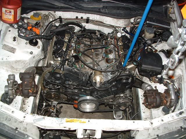
I could not get over how much I loved Hotlava's tt setup and it overcame me. So I figured at some point in the future I also wanted to do a tt setup and began slowly buying the additional pieces it would take to do so (being that many are the same, such as injectors, fuel pump monitoring gauges and what not). Then last week my car decide to get some garage time (it broke down later found to be a broken axle, Ebay? I think it was tsk tsk). But none the less it was a perfect excuse to play while she was down so I started to look at how I would eventually want my tt to be setup. What better way than to play. It helps kill concepts that look good in your head given the (not so) workable space; a few of my ideas have since died. But long story short this is where I am at so far. Now that my wife knows that it is just a broken axle I only have shipping time to continue playing before having to put her back together again.

A couple quick notes

-No this will not be done/completed for a very very long time.-This is very new to me so I would be the last to ask for suggestions though I love to share ideas.
-Yes the supercharger project is still underway and taking precedence over this.

-No I did not wake up one morning and say I am going to do a Legend Twin turbo setup during breakfast (sorry Hybird, that just kills me lol)
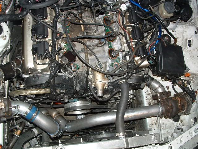
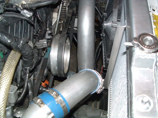
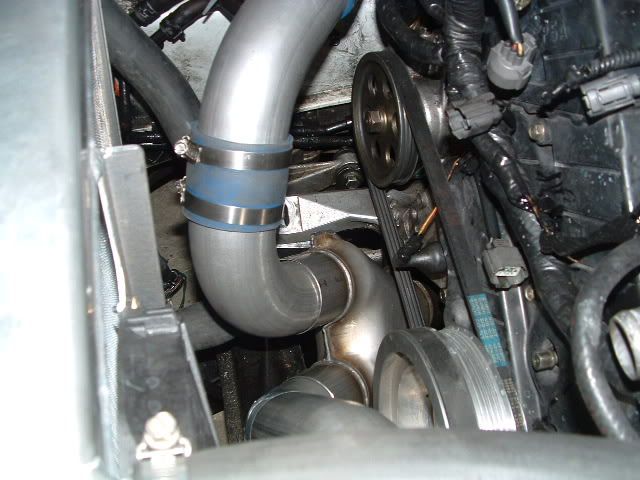
-No I am not going to be using PVC intercooler piping it is just cheaper to hack away at till I figure how I am going to do it when the time comes.
-I have also read up on some articles of Twin vs. Single and each seem to have there advantages from knowlegable members of their respective forums.
-cheap clamps will be replaced with t-clamps.

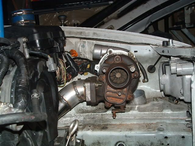
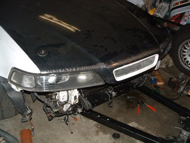
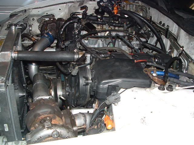
Ok the book is done here's the pics. (excuse the mess my garage is at war)
also please forgive the ugly "stand in" mesh and terrible paint, looks will come last. I don't want to tear it up after doing body work and paint.
Image


Image


Image


Image


Image


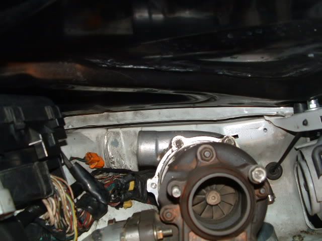
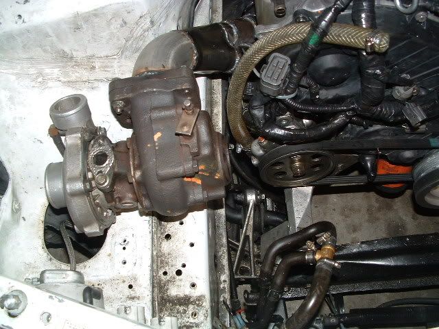
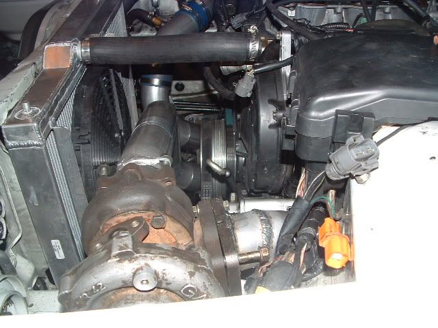
This one concerns me, there is not much rook and there is a damn brake fluid line that may need to be relocated. wires and hoses I don't mind moving brake, AC, and power steering lines I am not so happy/experinced with.
Image


Hopefully at some point I will be done destroying my car and be able to build it up like the one in my head lol.

-Tip- If you get a new intercooler or radiator, cover the fins with cardboard until it is fully installed so you don't damage the fins during installation :hide:

PS. The purple finish and and nice shiney engine bay will be back in time. it was too hard to maintain and not scratch to hell while getting a bug of some sort and doing stuff like ^ this. I think eventually I will powdercoat vs. paint though.
 
#477 ·
Thanks Kho :), and I do agree regarding the rising rate FPR which is why I will not be going this direction I would prefer to go with something that has its finger on teh pulse. and will do!

DeeandDee, I have not weighed them yet but they're not light in the header world due to how thick they are, but as Khow said they are stout :) I will probably clean them up a bit before weighing them.
 
#479 ·
^ were diving into ECU speculation territory here but I will touch on it for now then come back when the time is ready. Brace yourself here comes some theory. As the car reaches an area of boost that yields a higher demand than what normal (for this build under daily circumstances require, basically at WOT) I will have it switch maps to one that is better laid out for higher demands of fuel based then as it returns back to normal (build specific driving) it will switch back to the primary maps, all hopefully via a vacuum switch that I have set aside. Now I now the ECU can make the instant switch, what I don't yet know is whether I am going to have to use something like "the missing link", or whatever, to get the ECU to be content with the additional psi. But again I will gain a better understanding with real live conditions after the car is fired up which is still far from now.
 
#480 ·
^Your ECU is designed to deliver fuel based on your manifold pressure and RPM. If you're at anything above atmospheric pressure, regardless of your RPM or throttle, your fuel curve will be able to deliver enough fuel (assuming it's tuned properly), no vacuum switching required. Essentially your fuel delivery will be based on different portions of the map as needed based on current conditions.
^^The fuel pressure switch is really only a crutch. Assuming a reliable fuel system (pump, fuel lines, filter, etc...), a qualified installation (nothing is going to leak, melt, or fatigue), and a good program in the ECU, fuel pressure should be VERY linear and consistant.
 
#482 ·
Assuming a reliable fuel system (pump, fuel lines, filter, etc...
This was why i was wondering about the pressure switch. I should have specified. Thats an expensive project to blow up because a filter got clogged or a pump failed. I guess my real question was/is do you think the blockforged internals can withstand it running lean in event of failure since its relatively low boost?
 
#481 · (Edited)
Good point and agreed, here's my curiosity, the map sensor detects 0 to 5v (within Beavedit or Tuner Pro 0.47 to 2.97 v) in order to see what pressure the manifold is under and simultaniously combines that data with the RPM level in order to deliver the appropriate amount of fuel for the engine (all speculative to when it is actually looking entirely at the ECU map which is another issue for another day).

So if I can change the values that it looks for to accomodate closer to 5v within the bin file and adjust the maps accordingly would it be suffient to accomodate that much more psi?

Now here is the second part of that (where the vacuum switch theory comes in. If I were to T in a vacuum switch that has some type of air restriction on it that would show say 2.97volts (or what ever psi that converts from) as 0.47v and 4.9v (converted from psi as 2.97v would it accomdate more boost in that 2nd map? Here is a completely ficticious analogy with numbers.

0.47v = 15psi
(atmospheric pressure + engine at idle or for this example 0 boost)

2.97v = 18psi
(the amount of psi the engine puts out at WOT say 3 psi over atm pres.)

Then lets say the vacuum switch is set at 3 psi triggering the 2nd set of maps which would have the same voltage values on the map but with data that is configured for a boost level that starts at 3 psi over WOT and goes up from there.

Ok now that I have completely confused myself and everyone else I really think I will need to see what happens when I get there.
 
#483 ·
I am guessing that in my analogy the ECU would recognize this and thow what I call a severe CEL. (one that limits the RPM's of the car to 4k) because it would still be looking for set parameters defined in the map in terms of fuel and if that's not present you get a fuel delivery CEL.

And in steps DV8 with a "That's why you should just get an EMS, lol, there's no guessing :)"
 
#484 ·
I was just talking about a simple inline fuel pressure switch wired to kill power to the coils if fuel pressure drops to zero from the pump going out or a clogged filter. I saw an NHRA funny car run dry once and it detonated and shot one of its pistons through the oil pan and about 25 feet into the ground. Now im pretty sure your Legend isn't going to be pushing 2000 horses, but still I just wanted to throw it out there if a $20 switch could insure you against catastrophic failure. Again, I have no idea if its necesary with your setup.
 
G
#487 ·
Telion I don't know if you have your mod list posted yet. So what fuel injectors are you planning to run the venom (any size) or dsm or pte? Just trying to give some help and if you need a suggestion we could help you out on the mod list.

Oh how is the power steering bottle working out?
 
#489 ·
It's updated, did I miss anything (turbos are a given) I didn't include unrelated mods.

So Joe my welding angel was kind enough to weld the drivers side header correction and I made sure I got the angle right this time

Image


Image


Image


Image


Seeing the hood close was a joy.
Image


And yes that there in this pic would be my power steering in it's stock location
Image


Image
 
#488 · (Edited)
Power steering bottle is working great and if I could get a phillips to do that I would be all for it, just kidding and youare correct I am not but I have to work with what I have and there is an alterior motive to it too, but they are cheaper :) lol thanks Chris.

Mod list for the build some on some not yet

TI cams
Ported exhaust side of the manifold
Walbro 255lph fuel pump
NOS fpr and Megan FPR (undecided)
DSM 450cc injectors
water injection cooling (still working on this have all the parts)
C&R racing radiator
dual oil cooler
custom aluminum oil reservoir for turbos
water temp, oil pressure, boost gauges
turbo timer.
Top fuel blow off valve
2 in 1 out intercooler
3" piping, barrel spun cat and N1 style exhaust
Innovate LM-1 and RPM converter box
Neo safc and possibly a few other things I am forgetting.
 
#490 ·
:yumyum:
 
#492 ·
so in that pic above it actually kinda looks like there might be enough room for nsx heads.....(bring on the flamin)
 
#495 ·
^ I agree 100% and thank you I can't wait for the next stage of your build which I am also watching :)

Legendfire my engine bay is deceptive; before thinking that there is an abundance of space in the engine bay please pop your hood and then if you decide to proceed you will know what you are getting into.
 
#496 · (Edited)
Ok I have some pics on how I want to route the exhaust, sorry none that show how it will route under the passenger side header yet. I have also desided to have a hot side and a cold side for my car so all of the plumbing that is on the hot side (passenger side are likely to be re-routed to the cold side (drivers side)

Image


Image


Image


Image


Image


Image


Still a great deal of work to do but this is a great start
***couplers will be replaced with welds once I feel good about the plumbing :) ***
Do not use couplers on the hot side
 
#497 ·
lol i was about to say.. those couplers are gonna melt really fast haha.. but i figured it was temporary, anyways its looking great! Your doing a great job documenting this :thumbsup:
 
#498 ·
Lol, Thanks, normally I woulddo it all and then post but I am enjoying dointg it this way more because alot of the advice and feed back I have received here have helped the build unfold. There's also part of that pic you asked about in routing the exhaust. :)
 
#500 ·
it is going to be re run with a custom made hose combining silicone and aluminum piping upper and lower.
 
#501 ·
I thought that might be the case.

hmm I wonder if you could use the space a little better by reversing the collector here. Just lengthen the passenger side tube a bit to reach the righthand input on the collector, running closer to the crankshaft pulley, then the same with the driver's side but closer to the radiator. Might create a safe passage for the lower hose.

Image
 
#502 ·
Possibly but I played with it a lot and that was the best I could come up with without needing to remove or modify the front suspension rack support bar, having sufficient room for spacing from the power steering belt and keeping an agle at the 3" exhaust side that would not be too much of a henderance on the exit path of the exhaust. I did find that I had a little more room than I anticipated once I put the radiator in though; so I may give it a second look tomorrow.
 
#505 ·
Not yet, I have another harness on standby incase I need it but I will worry about wiring last unless I get bored.
 
#507 ·
Thanks, I think I am going to open up the holes a bit where the washer fluid and stock air box are today to decrease the amount of piping required to get to the IC. possibly more pics later.
 
#510 ·
^lol, now there is a wild and crazy idea :)